
InJoint
Customized total ankle replacement
InJoint is a non-cemented implant for arthritic ankle joints — osteoarthritis, post-traumatic arthritis or rheumatoid arthritis. Where total ankle arthroplasty once offered surgeons very limited choice, InJoint gives them a truly personalised mobile-bearing ankle implant.
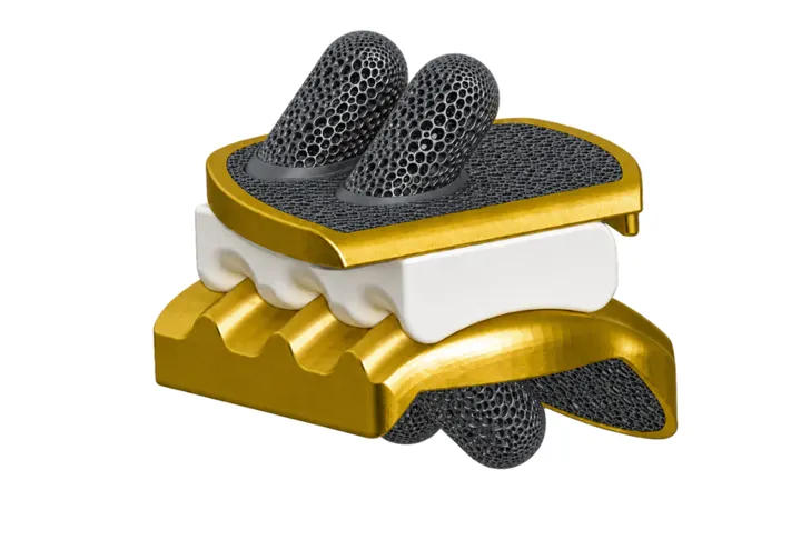
Engineered around the patient's anatomy
Perfect fit
Sized to that patient's own joint, reducing the risk of overhang or underhang-related pain.
Bone preserving
A design that needs significantly less talus resection than conventional systems.
Curved tibial chamfer
The curved tibial resection chamfer reduces the risk of malleolar fracture.
Simple instrumentation
Customised, simplified instruments for surgical efficiency in theatre.
Mobile bearing
A personalised mobile-bearing construct for arthritic ankles — osteoarthritis, post-traumatic or rheumatoid.
This implant in theatre
 Ankle
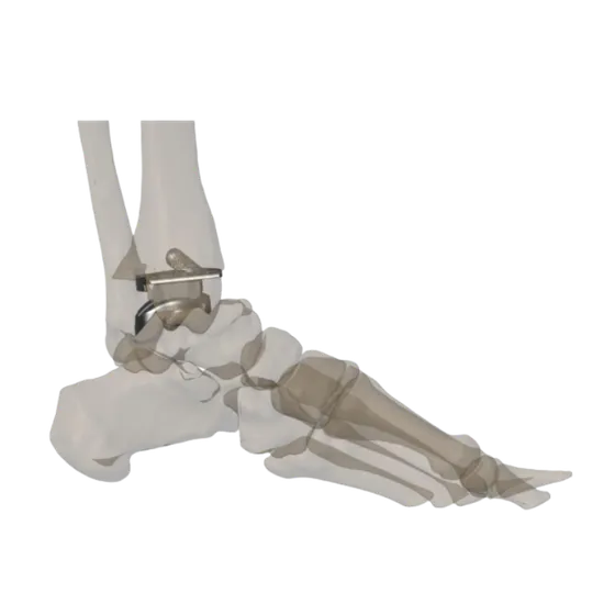
AnkleCustom Total Ankle Replacement Using a Patient-Specific 3D-Printed Implant
A 48-year-old female with advanced osteoarthritis of the left ankle, where complex biomechanics and unique anatomy made conventional implant reconstruction difficult.
Read the case →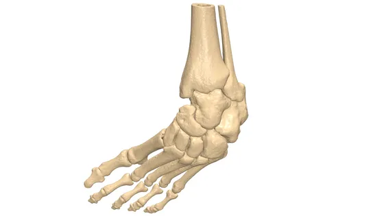 Foot & ankle
Club Foot Virtual Planning
Virtual osteotomy sequence and pre-op model for congenital talipes equinovarus
Read the case →Reference Documents
Total ankle replacement — surgical technique
The full patient-specific technique for the InJoint custom total ankle replacement — pre-operative planning, resection parameters and twelve intra-operative steps executed with patient-specific instrumentation.
Pre-operative planning
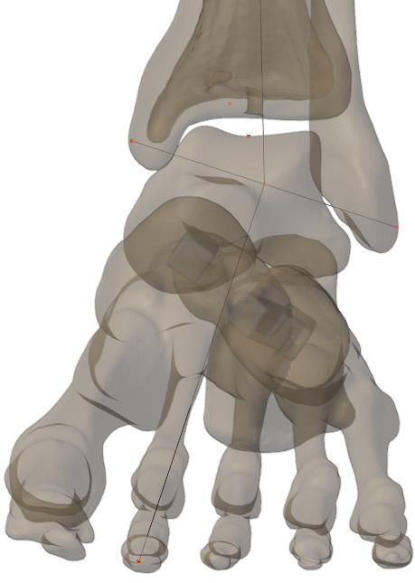
Landmarks and axes are defined on the segmented model: medial and lateral malleoli, tibia proximal point, tibia and talus deepest points, ankle centre, foot midpoint and midline, giving the tibial mechanical axis and the ankle rotation axis. Dorsiflexion is corrected by rotating about the talus geometrical centre along the ankle rotation axis to restore a normal ankle position.
Resection parameters
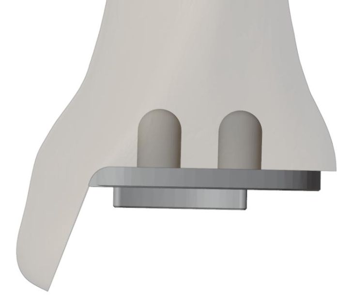
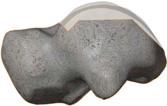
Tibia: resection approximately 7 mm from the deepest point of the distal tibial surface, then drilled Ø7 mm to accommodate the implant pegs. Talus: proximal resection approximately 4 mm from the deepest point, anterior and posterior chamfers matched to the implant, and peg holes drilled; the implant curvature radius is matched to the actual talar radius. Where the talar curvature is deformed, the contralateral side is used as reference.
Surgical steps
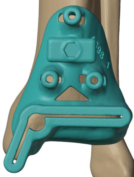
Place the PSI tibial guide on the anterior distal tibia so it seats naturally in the planned position without gaps, slope or movement. Hold it with the hex holder and insert two 2.5 mm pins distally, omitting the proximal pin. Soft tissue must be stripped for a proper fit.
Instruments: Two 2.5 mm pins, tibia resection guide, hex holder
Prepare the ankle rod assembly and place it on the tibial resection guide, using the patient-specific proximal guide for better rod positioning.
Instruments: Ankle rod, rod housing, skin guide, tibia resection guide
Align the C-arm on the reference pins and verify guide position in the coronal plane, then on the K-wire for the sagittal plane — the ankle rod should be parallel to the tibial mechanical axis in both. Confirm the cutting direction with the angle wing in both planes.
Instruments: Ankle rod assembly, K-wire and housing, angle wing, 2.5 mm pins
Remove the resection guide leaving the distal pins, fit the perforation guide, secure the proximal pin and perforate with a 5 mm drill — using a distractor to open the joint space so the talus is not damaged. Then fit the cutting guide, protect the fibula with a lateral pin, drill medially at 3 mm then 5 mm, and resect the tibia with the saw.
Instruments: Perforation and cutting guides, 3 & 5 mm drills, four 2.5 mm pins, cutting saw
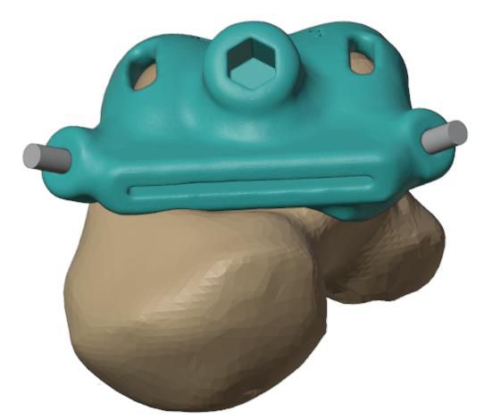
Plantarflex the foot and seat the talar PSI guide in its single planned position, fixed with two cross pins and no clearance to bone. Verify resection depth and orientation with the angle wing under AP and lateral fluoroscopy, then resect with the saw.
Instruments: Two 2.5 mm pins, talus proximal resection guide, hex tool, angle wing, cutting saw
Check the resected surface against the proximal verification guide — the contour should match. Insert two parallel pins through the guide and use its posterior surface to make the posterior talar resection.
Instruments: Two 2.5 mm pins, talus proximal verification guide, resection saw
Bring the ankle to 45° plantarflexion before placing the chamfer guide. Drill anteriorly with a 5 mm flat-end mill through the chamfer drill guide, then swap to the chamfer slot guide and complete the cut.
Instruments: Talus chamfer drill and slot guides, 5 mm flat-end mill, two 2.5 mm pins
Place the PSI peg drill guide on the resected talus and pin it. Drill through the 3 mm insert, then the 5 mm insert, and finish with a 7 mm ball-end mill.
Instruments: Talus drill guide, 3 & 5 mm drill inserts and bits, 7 mm ball-end mill
Seat the talar implant on the resected talus and use the impactor to confirm fit.
Instruments: Talus implant, implant impactor
Verify the resection gap with trials matching the tibial and poly implant thickness; if fitment is unsatisfactory, take a +2 mm resection, re-check, and if needed a +4 mm resection. Then secure the tibial peg hole guide and drill 3 mm, 5 mm and finally a 7 mm ball-end mill.
Instruments: Implant trials, +2/+4 mm resection guides, tibia peg drilling guide, drill inserts and bits
Place the tibial implant on the resected tibia and confirm fit with the impactor.
Instruments: Tibia implant, implant impactor
With both metal components secured, insert the poly bearing with the inserter. Thickness is determined by the trial; 5, 6, 7 and 8 mm are available.
Instruments: Poly implant, poly inserter
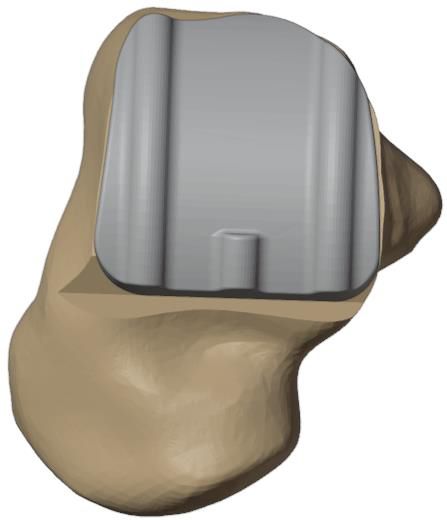
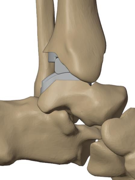
Confidential — Jajal Medical's intellectual property.
India's first patient-specific 3D-printed custom total ankle replacement: a case report
Dhanopeya A, Upadhyay P, Hegde H, Mattoo R, Oberoi N, Saxena A. Department of Orthopaedics, Max Smart Super Speciality Hospital, Saket, New Delhi.
India's first patient-specific, 3D-printed custom total ankle replacement, performed for end-stage post-traumatic tibiotalar arthritis.
Case
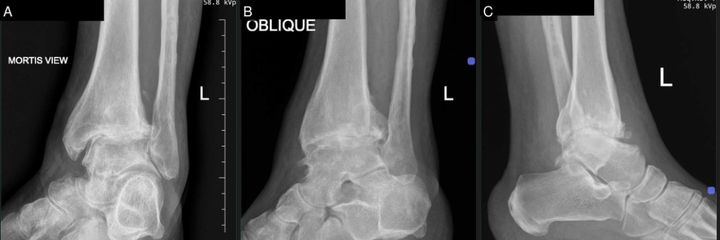
A 48-year-old woman with a left ankle fracture in 2017 treated by ORIF and staged implant removal presented with progressive pain, early-morning stiffness and a functionless arc of motion. Weight-bearing radiographs showed severe tibiotalar joint-space narrowing, subchondral sclerosis and cysts with anterior osteophytes; MRI confirmed full-thickness cartilage loss with synovitis. Conservative treatment had failed, and after counselling on arthrodesis versus arthroplasty she chose motion-preserving replacement.

Planning and implant design
- High-resolution CT segmented in MySegmenter to build the 3D anatomical model.
- Digital plan set the ankle axis correction, dorsiflexion optimisation, tibial and talar resections, implant geometry, sizing and alignment.
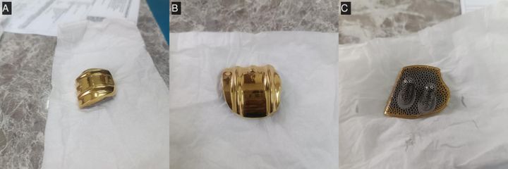
- Implant manufactured by electron-beam melting in Ti-6Al-4V with dual-peg fixation, a porous trabecular ingrowth surface, a precision-machined UHMWPE insert and a titanium-nitride wear coating.
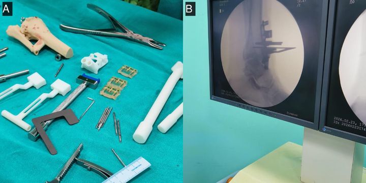
- SLA resin prototypes and FDM/PLA bone models allowed bench rehearsal with the patient-specific cutting guides.
Surgery
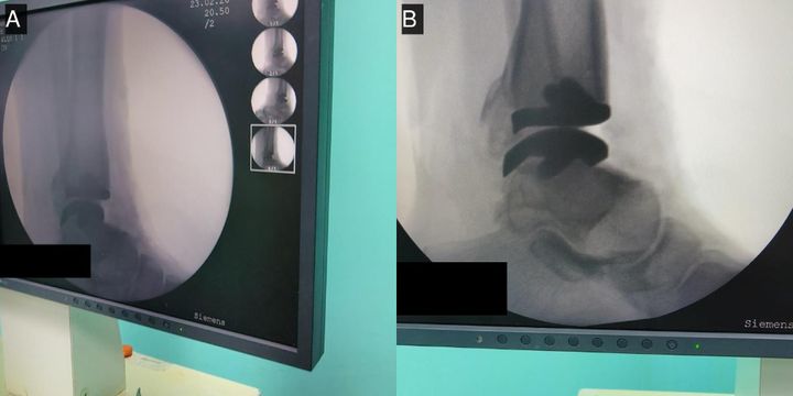
Performed through a standard anterior approach in 32 pre-planned steps using patient-specific guides and custom instruments. Guides seated reproducibly on the bony landmarks and resections were confirmed under image intensification; tibial and talar components were implanted with a 6 mm polyethylene insert, and a tendo-Achilles lengthening corrected the equinus.
Outcome at six months
| Outcome measure | Pre-op | 6 months |
|---|---|---|
| AOFAS ankle–hindfoot score (/100) | 4 | 88 |
| VAS pain score (0–10) | 7 | 0 |
| Dorsiflexion | 0° | 7° |
| Plantarflexion | 0° | 5° |
| Total sagittal arc | 0° | 12° |
| Hindfoot inversion–eversion | 0° | 10° |
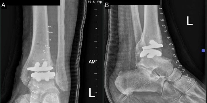
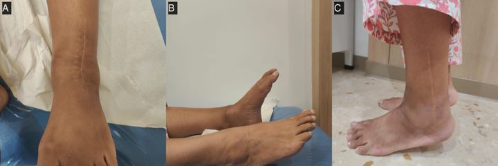
Follow-up radiographs showed satisfactory component position with no loosening, migration or subsidence against established criteria (peri-prosthetic lucency under 2 mm, no migration over 5 mm or 5°, no subsidence of 5 mm or more). The patient was very satisfied and returned to routine activities with minimal discomfort.
Discussion
Each generation of standard total ankle prosthesis carries characteristic technical failure modes — aseptic loosening, subsidence, malalignment and impingement — driven by imprecise fit, fixation and alignment in anatomically altered post-traumatic ankles. A fully patient-specific construct targets those technical drivers directly by reproducing individual anatomy and restoring alignment; biological failure modes and long-term durability remain to be proven, and continued surveillance is planned.
Summary of the case report, reproduced with the authors' figures. Patient identifiers redacted.
Planning a case? Send us the CT.
Send an anonymised scan and get your first 3D visualisation back within 24 hours.